The starting air system consists of the manoeuvring system
and the starting air
components. The following
items are described:- Manoeuvring System, Main Starting Valve, Starting Air Distributor, Starting Valve.The manoeuvring system is of electric/pneumatic design.
It is designed for
remote control from engine control-room and/or bridge.
The system consists of two or three sub-systems:regulating system, reversing system (only reversible engines), and safety system.
Regulating system: With the regulating system it is possible to start, stop and control the
engine.The
START and STOP functions are controlled pneumatically.
Speed-setting during remote control: During remote control, the speed-setting is controlled by
the control handle on the manoeuvring console, which sends a signal to the governor system.The
engine speed depends on the magnitude of the signal. The governor system will maintain this speed independently of
the engine load.
speed-setting durinq manual control: During control from the engine side control console, the
governor is dis-connected from the fuel pumps, and the speed control is effected through the regulating handwheel.
Reversing system: The reversing
system contains two pneumatic valves (AHEAD and
ASTERN).
These valves
control the air cylinders for reversing the fuel pump rollers and the starting air distributor.
The safety system
is separately supplied with air and is controlled by the engine monitoring system (with separate power
supply). In the event of shut-down,
the safety system leads an air signal to the puncture valve on each fuel pump, thereby cutting off the delivery
of high-pressure fuel oil, after which
the engine stops. large valve. Both valves are operated by pneumatic actuators. The
safety system is connected during all modes of engine control.


The starting air
distributor is fitted to the chain casing and is driven directly from the aft end of the camshaft.It controls the starting valves.When START is ordered, duct R of the
starting air distributor is pressurized and the spring-loaded distributor pistons are forced towards the cams because of a difference in the diameters.Those pistons which are resting on the lowest section of
the cams allow control air to pass through the bores in the starting air distributor to
the starting valves,
which open.The engine
will now rotate on starting air.When FUEL is ordered, duct R
is vented, and no further starting valves will open.However, those distributor pistons which already
rest on the lowest section of the
cams are kept down because, in this position, ducts R are blocked
by the distributor pistons themselves.When the cams lift the distributor pistons at the end of
the starting period, ducts R are unblocked and vented.This function enables the connected cylinders to finish
the starting period.For reversible engines reversing of the starting air
distributor is carried out by means of an air cylinder which displaces the shaft of the starting
air distributor
axially, to engage the set of cams which corresponds to the ordered direction of rotation.

The starting valve
(spring-loaded) is fitted on the cylinder cover. It is controlled by control air from the starting air distributor. When the main starting valve is open, chamber P of
the starting valve is pressurised through the starting air pipe(30 bar).The starting valve is kept closed by the spring. When
chamber U above the piston of the starting valve is pressurised with control air from the
starting air
distributor, the starting valve opens, and starting air now flows from the starting air pipe to the cylinder.When the
starting period is finished, chamber U is vented through the vent pipe of the starting air distributor, and the
starting valve will close.The starting air in chamber P and the starting air pipe are vented
slowly through small holes
in the starting air pipe.

credit to SP handout
·
Reducing valve – 30
bar to 7 bar - The above sketch, an air reducing valve, is fitted on the outlet
of compress air bottle for the use of Working air, M/E,
G/E control and safety system, Purifier control,
Back flush filters, E / R overhead pneumatic crane, etc....
High pressure air enters under the valve. The spring, acting on the spindle,
open the valve and air pass to the reduced pressure side. The compression of
the spring controls the opening of the
valve. If the opening increases, the higher pressure obtained on the other side,
acts to close down the valve to
normal lift, and therefore the correct reduced pressure will be maintained. A relief valve is fitted on the low pressure side
to prevent excessive pressure on the reduced
air line.

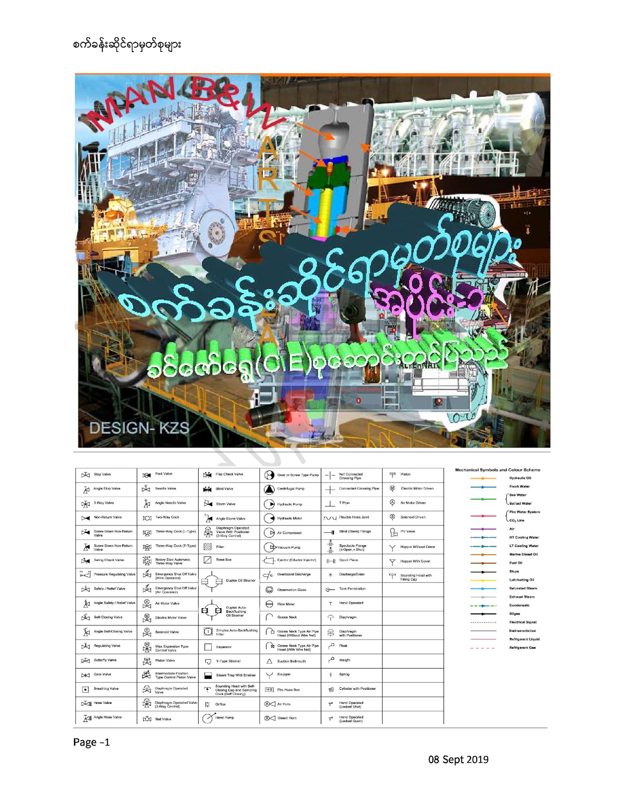
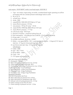
- 2 stroke MAN B&W MC engine
(6S50MC အင္ဂ်င္အတြက)္ နဲ႔ပက္သက္ရင္ေတါ႔
-
Starting system ကိုၿကည္႔ရင ္ reducing valve အထြက္ကလါတဲ႔ 7 bar control air ဟါ
လိုင္း၂ခုအဓိကခြဲသြါးတယ္။တခုက turning gear interlock ကိုၿဖတ္တယ္။

ေနာက္တလုိင္းကဘါကိုမၿဖတ္ဘဲ air starting ball valve ဆီတန္းသါြးၿပီး ball valve close position ကိုထိန္းထါးတယ္။အဲဒီလိုင္းကဘဲ stop signal ေပး၇င္ puncture valve ကို activate လုပ္ဖို႔။valve 117 ကို stop signal ၇ီွ၇င္ distributor ကေလ drain လုပ္တါ၇ပ္ၿပီး start signal ေပး၇င္ distributor ကေလေပးတါကိုလုပ္ဖို႔အသင္႔လုပ္ထါးတယ္။ဒီမွာမွတ္သါးစ၇ာက stop signal ဟါ fuel lever ဆီေက်ြးတဲ႔အမွတ္ေ၇ာက္မွေပ်ာက္တယ္ဆိုတါဘဲ၊
အင္ဂ်င္နိုးဘို႔လိုတါက
၁-distributor ahead / astern ကေပးတဲ႔ order နဲ႔ကိုက္ဖို႔
2-fuel pump timing က ahead/ astern order နဲ႔ကိုက္ဖို႔
၃-air starting ball valve ကိုဖြင္႔ဖို႔
၄-aဒါေတြကအဓိကမဟုတ္လါး
အခု manoeuvring lever stop positionမွာvalve 117က distributor ကို drain လုပ္တါ၇ပ္ၿပီးအသင္႔အေနအထါးလုပ္ထါးၿပီ။ေနာက္ၿပီး air starting ball valve ကို 2 POSITION 5 WAY VALVE 27ကေနတဆင္႔ေလေပးထါးၿပီ။ 27 ကို POSITION ေၿပာင္းဖို႔ ACTIVATE လုပ္လုိက္တါနဲ႔ BALL VALVE ပြင္႔တဲ႔ POSITION ေ၇ာက္သြါးလိမ္႔မယ္။
TELEGRAPH
AHEAD POSITION - တကယ္လို႔ AHEAD နိဳးၿ႔ပီးသါး STOP ကေနေနာက္တခါ AHEAD ထပ္နိဳးတါမဟုတ္ရင္
။ local ကနိုးတါမဟုတ္၇င္ ahead valve 86 ( 2position, 3 way
valve) activate ၿဖစ္တယ္။
AHEAD VALVE - ၈၆ကေန၂လုိင္းခြဲသြါးတယ္။
တခုက1 –[[ fuel pump roller ကို ahead / astern position ေၿပာင္းေပးတဲ႔ reversing
cylinder 13 ကိုသြါးၿပီးေလေပးတဲ႔။ 2- AIR DISTRIBUTOR AIR CYLINDER AHEAD ကိုေ၇ြ႔ေပးတဲ႔ VALVE 14 ကိုေလေပးတဲ႔]]----(၁) VALVE 10ကို ACTIVATE လုပ္ထါးတယ္။( အဲဒီေလက fuel run signal လါၿပီး၆ sec ၿကာၿပီးမွ drain လုပ္တယ္။) ၈၆ကလါတဲ႔ေနာက္တလုိင္းက AIR DISTRIBUTOR AHEAD OR ASTERN
POSITION ဘယ္ POSITION မွာ၇ိွေနလဲဆိုတါစစ္တဲ႔ END POSITION VALVE FOR AHEAD (၂) VALVE 55ကိုသြါးတယ္။ DISTRIBUTOR AHEAD POSITION မွာ၇ိွလို႔ VALVE 55 ACTIVATE ၿဖစ္၇င္အဲဒါကိုၿဖတ္တဲ႔ CONTROL AIR SIGNAL ကဗါး၃၇မွာသြါးေစါင္႔ေနတယ္။ ( START SIGNAL လါတဲ႔အထိ)
Manoeuvring
LEVER START POSITION – START
VALVE 90ကိို ACTIVATE လုပ္မယ္။သူကလါတဲ႔ေလကVALVE 37ကိုဖြင္႔ေပးလို႔ခုနင္က TELEGRAPH AHEAD တံုးကဗါး၃၇က control air signal ကဆက္သြါးၿပီးvalve 33ကိုသါြး activate လုပ္တယ္။ဒီေတါ႔ဗါး၃၃၇ိွ turning gear interlock ကိုၿဖတ္လါတဲ႔ control air က၃လိုင္းခြဲၿပီးထြက္သြါတယ္။ပထမတလိုင္းက distributor အ၀င္ manual valve( ခါတိုင္း cyl head air start valve လံုမလံုစမ္း၇င္ပိတ္ေနက်) ကလါတဲ႔ 30 bar ေလကို(1) valve 26( distributor supply
valve)ကတဆင္႔ distributor ဆီကိုဖြင္႔ေပးတယ္။ဒုတိယလိုင္းက air start ball valve ကိုဖြင္႔တဲ႔ signal ေပးတဲ႔(2) ဗါး၂၇ ( open valve
for air start ball valve)ကိုသြါးဖြင္႔တယ္။တတိယလိုင္းကအင္ဂ်င္စနိဳးခ်ိန္ air distributor disc ၇ုတ္တ၇က္လည္လို႔ distributor air cylinder မနာေအါင္ lock လုပ္တဲ႔(3)ဗါး၁၄( distributor lock valve )ကို activate လုပ္တယ္။
အခု starting air နဲ႔အင္ဂ်င္လည္သြါးၿပီၿဖစ္တယ္။ Ahead rpm 10 or astern rpm 11 ေ၇ာက္တါနဲ႔ fuel on signal လါပါတယ္။ အဲဒါလါတါနဲ႔ stop signal ေပ်ာက္ပါတယ္။ဒီေတါ႔၁၁၇ valve က 1 sec အၿကာမွာ drain ၿဖစ္ပါတယ္။ puncture valve ကိုဖြင္႔ထါးတဲ႔ေလလဲdrain ၿဖစ္လို႔ဆီေက်ြးပါတယ္။ Reversing cylinder ကေလက၆ sec ၿကာ၇င္ drain ၿဖစ္ပါတယ္။ Start signal လဲေပ်ာက္လို႔ air start ball valve ပိတ္ပါတယ္။valve 26 distributor supply air ပိတ္ပါတယ္။
Astern အတြက္ကေတါ႔ဗါးနံပါတ္ေတြကြါသြါးေပမဲ႔အလုပ္လုပ္ပံုတူပါတယ္။
Valve 86= astern valve 88 , valve 10 = astern valve 11,valve 55 = astern valve
56,valve 14= astern valve 15
ၿဖစ္ရပ္တခုကေတာ႔ - At 10:00 LT, carried out main engine starting test in both
the ahead & astern direction with bridge control in the presence of Inspectors.
Ahead start test was successful but the first 2 astern starting tests failed.
Main engine managed to start on astern direction at the 3rd attempt
slowly and started normally at the 4th attempt. Troubleshooting by crew revealed that the pneumatic valve
No.88 ( Two-position three way solenoid valve) found had slight air leakage.
Overhauled the faulty pneumatic valve No.88 observed internal have slight dirt
inside. Carried out main engine starting test in ahead and astern direction
several times. Engine starting response found satisfactory and reported to
office. The
valve No.88 was located at the main engine local control platform and fitted
inside a cabinet together with valve No.84, 86, 90.(လံုး၀မလည္တါမ်ားပါတယ္)
ဗါး ၈၈ သို႔ ၈၆
မေကာင္းတါဆိုမလည္တါမ်ားပါတယ္။သူပံုမွန္လုပ္လို႔ လည္ရင္အင္ဂ်င္ႏွိဳးပါတယ္။ir distributor ကလိုခ်င္တဲ႔ဆလင္ဒါကို pilot air signal ေပးဖို႔

S
Comments
Post a Comment